| C | Cr | Fe | S | Mn | Si | Ti | Cu | P | Al | La | N | W | Nb | Ni | Zr | ||
|---|---|---|---|---|---|---|---|---|---|---|---|---|---|---|---|---|---|
| Crofer 22 APU | MIN | 20.0 | Bal | 0.30 | 0.03 | 0.04 | |||||||||||
| MAX | 0.03 | 24.0 | 0.020 | 0.80 | 0.50 | 0.20 | 0.50 | 0.050 | 0.50 | 0.20 | |||||||
| Crofer 22 H | MIN | 20.0 | Bal | 0.10 | 0.02 | 0.04 | 1.0 | 0.20 | |||||||||
| MAX | 0.030 | 24.0 | 0.006 | 0.80 | 0.60 | 0.20 | 0.50 | 0.050 | 0.10 | 0.20 | 0.04 | 3.0 | 1.00 | 0.50 | |||
| ZMG232L | Typical | 0.02 | 22 | Bal | 0.5 | 0.1 | 0.1 | 0.07 | 0.25 | ||||||||
| ZMG232G10 | Typical | 0.02 | 24 | Bal | 0.3 | 0.1 | 0.1 | 0.07 | 2 | 0.25 | |||||||
Technical Documentation:
Other Materials:
We also accept orders for parts made of ferrite alloys for SOFC interconnectors, stainless steel such as SUS430, and heat-resistant alloys such as Inconel. Please feel free to consult with us.
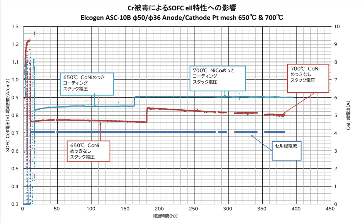
The graph below shows the measured differences in the initial characteristics of SOFC interconnectors with and without CoNi plating treatment.
The graph below shows the single-cell output voltage over time when the same constant current is applied to a single-cell stack. The coated single-cell stack shows better characteristics in terms of voltage variation over time and performance.
This CoNi plating can be applied to materials other than metal interconnectors that require maintaining high electrical conductivity, such as current collectors. Please consult with us.
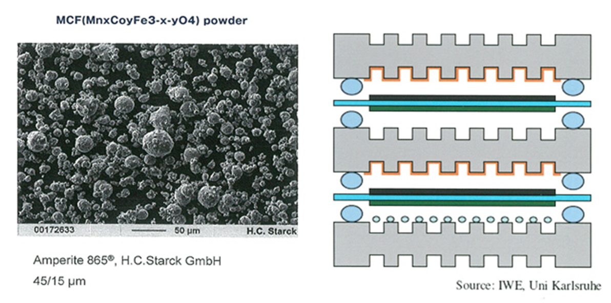
Similar to Co-Ni plating, a coating process by spraying MCF powder is available as a method to maintain good electrical conductivity for a long period of time at SOFC operating temperatures and to suppress Cr evaporation from metal interconnectors.
MCF (MnxCoyFe3-x-yO4) powder from Höganäs is used for this coating process.
Magnex Co., Ltd. also accepts orders for coating treatment of MCF.
The above photograph is an SEM photograph of a thermal spray deposition using Höganäs MCF powder (Amperit 865®/particle size: 45-15 μm) under standard thermal spraying conditions.
For more information on MCF powder, please see SOFC/SOEC Powder & Paste.
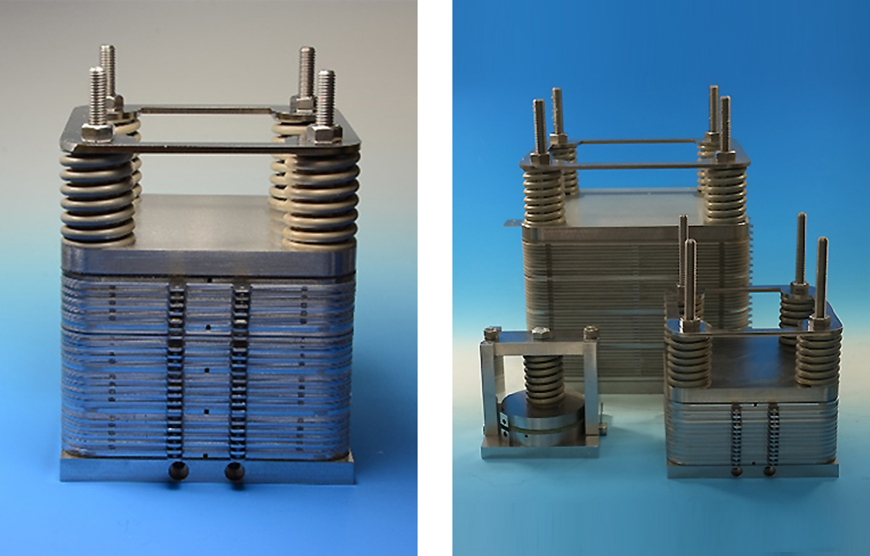
Ceramic springs are used when constant pressure is applied to the stack.
It has the following characteristics and has the same pressurization performance at SOFC/SOEC operating temperatures as at room temperature.
| item | unit | MGS | ||||||||
|---|---|---|---|---|---|---|---|---|---|---|
| 020S | 020L | 025S | 025L | 030S | 030L | 050S | 050L | 060S | ||
| Maximum load | (kgf) | 2.0 | 2.0 | 2.5 | 2.5 | 3.0 | 3.0 | 5.0 | 5.0 | 6.0 |
| (N) | 19.6 | 19.6 | 24.5 | 24.5 | 29.4 | 29.4 | 49 | 49 | 58.8 | |
| displacement | (mm) | 4 | 8 | 2.5 | 3.1 | 3 | 4.3 | 3.8 | 5 | 4 |
| spring constant | (N/mm) | 4.9 | 2.5 | 9.8 | 7.9 | 9.8 | 6.8 | 12.9 | 9.8 | 14.7 |
| wire diameter(d) | (mm) | 1.65 | 1.65 | 1.65 | 1.65 | 1.8 | 1.8 | 2.2 | 2.2 | 2.5 |
| free length(L) | (mm) | 14.3 | 26.5 | 20.7 | 25.4 | 24.0 | 33.3 | 27.4 | 34.7 | 30.1 |
| Coil Outer Diameter | (mm) | 18.4 | 18.4 | 13.2 | 13.2 | 14.4 | 14.4 | 17.6 | 17.6 | 20.0 |
| Maximum Deflection(F) | (mm) | 4.0 | 8.0 | 2.5 | 3.1 | 3.0 | 4.3 | 3.8 | 5.0 | 4.0 |
| Minimum Height(L-F) | (mm) | 10.3 | 18.5 | 18.2 | 22.3 | 21.0 | 29.0 | 23.6 | 29.7 | 26.1 |
| item | unit | MGS | ||||||||
|---|---|---|---|---|---|---|---|---|---|---|
| 060L | 080S | 080L | 090S | 090L | 140S1 | 140L1 | 140S2 | 140L2 | ||
| Maximum load | (kgf) | 6.0 | 8.0 | 8.0 | 9.0 | 9.0 | 14.0 | 14.0 | 14.0 | 14.0 |
| (N) | 58.8 | 78.4 | 78.4 | 88.2 | 88.2 | 137.2 | 137.2 | 137.2 | 167.2 | |
| displacement | (mm) | 6 | 4.7 | 7.3 | 4.5 | 6.9 | 5.6 | 8.2 | 5.6 | 8.2 |
| spring constant | (N/mm) | 9.8 | 16.7 | 10.7 | 19.6 | 12.8 | 24.5 | 16.7 | 24.5 | 16.7 |
| wire diameter(d) | (mm) | 2.5 | 2.8 | 2.8 | 3.0 | 3.0 | 3.5 | 3.5 | 4.1 | 4.1 |
| free length(L) | (mm) | 43.4 | 33.4 | 49.7 | 32.9 | 48.4 | 39.8 | 56.2 | 26.5 | 34.4 |
| Coil Outer Diameter | (mm) | 20.0 | 22.4 | 22.4 | 24.0 | 24.0 | 28.0 | 28.0 | 43.0 | 43.0 |
| Maximum Deflection(F) | (mm) | 6.0 | 4.7 | 7.3 | 4.5 | 6.9 | 5.6 | 8.2 | 5.6 | 8.2 |
| Minimum Height(L-F) | (mm) | 37.4 | 28.7 | 42.4 | 28.4 | 41.5 | 34.2 | 48.0 | 20.9 | 26.2 |
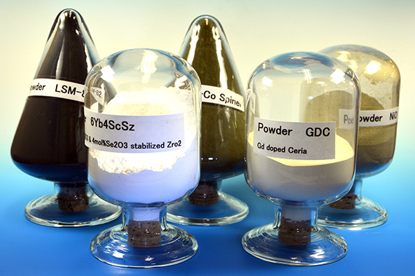
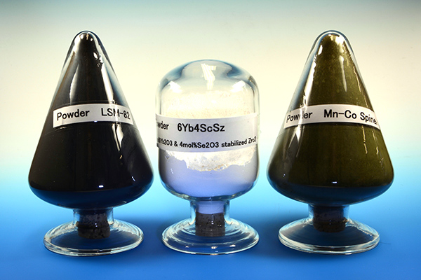
We are the Japanese distributor for Höganäs and Kceracell, and offer high-quality powders for SOFC cell cathodes, anodes, and electrolytes.
We also offer several grades according to specific surface area. We can also supply powders for interconnector protective coatings and powders for plasma spraying.
| Name | Composition | BET (m2/g) | Typical Properties and Applications |
|---|---|---|---|
| LSM20 | La0.75Sr0.20MnO3 | 4.0~6.0 |
|
| LSM30 | La0.65Sr0.30MnO3 | 1.5~3.5 |
|
| LSCF | La0.6Sr0.4Co0.2Fe0.8O3 | 7.5~10.0 |
|
| LSMC | La0.8Sr0.2Co0.1Mn0.9O3 | 1.5~3.5 |
|
| LSC10 | La0.9Sr0.1CoO3 | 4.0~6.0 |
|
| LSC40 | La0.6Sr0.4CoO3 | 4.0~6.0 |
|
| LSC50 | La0.5Sr0.5CoO3 | 4.0~6.0 |
|
| MCF | Fe0.05Co0.95MnO4 | 2.0~4.0 |
|
| 10GCO | Gd0.1Ce0.9O2 | 6.0~9.0 |
|
| 10GCO fine Grade | Gd0.1Ce0.9O2 | 10.0~13.0 |
|
| 20GCO | Gd0.2Ce0.8O2 | 6.0~9.0 |
|
| 20GCO fine Grade | Gd0.2Ce0.8O2 | 10.0~13.0 |
|
| 40GCO | Gd0.4Ce0.6O2 | 10.0~13.0 |
|
| Name | Composition | SSA m2/g |
|---|---|---|
| LSM-73-N | (La0.7Sr0.3)0.95MnO3 | 10~15 |
| LSM-73-F | (La0.7Sr0.3)0.95MnO3 | 5~10 |
| LSM-73-C | (La0.7Sr0.3)0.95MnO3 | 1~5 |
| LSM-82-N | (La0.8Sr0.2)0.98MnO3 | 10~15 |
| LSM-82-F | (La0.8Sr0.2)0.98MnO3 | 5~10 |
| LSM-82-C | (La0.8Sr0.2)0.98MnO3 | 1~5 |
| LSCF-6428-N | (La0.6Sr0.4)0.97Co0.2Fe0.8O3 | 10~15 |
| LSCF-6428-F | (La0.6Sr0.4)0.97Co0.2Fe0.8O3 | 5~10 |
| LSCF-6428-C | (La0.6Sr0.4)0.97Co0.2Fe0.8O3 | 1~5 |
| LSC-64 | La0.6Sr0.4CoO3 | 5~10 |
| LSF-82 | La0.8Sr0.2FeO3 | 5~10 |
| LNF-64 | LaNi0.6Fe0.4O3 | 5~10 |
| BSCF-5582 | Ba0.5Sr0.5Co0.8Fe0.2O3 | 5~10 |
| SSC-55 | Sm0.5Sr0.5CoO3 | 5~10 |
| Name | Composition | SSA m2/g |
|---|---|---|
| 8YSZ | (Y2O3)0.08(ZrO2)0.92 | 10~15 |
| 6Yb4ScSZ | (Yb2O3)0.06(Sc2O3)0.04(ZrO2)0.9 | 10~15 |
| GDC-10-N | Gd0.1Co0.9O1.95 | 10~15 |
| GDC-10-F | Gd0.1Co0.9O1.95 | 5~10 |
| GDC-20-N | Gd0.2Co0.8O1.9 | 10~15 |
| GDC-20-F | Gd0.2Co0.8O1.9 | 5~10 |
| SDC-20-N | Sm0.2Co0.8O1.9 | 10~15 |
| SDC-20-F | Sm0.2Co0.8O1.9 | 5~10 |
| LSGM-9182 | La0.9Sr0.1Ga0.8Mg0.2O2.85 | 3~6 |
| LSGM-8282 | La0.8Sr0.2Ga0.8Mg0.2O2.8 | 3~6 |
Sintered granule for air plasma spray coating
| Name | Composition | PSD µm |
|---|---|---|
| APS-E | All Electrolyte | D50=20~40 |
| Name | Composition | SSA m2/g |
|---|---|---|
| NiO-AFL | NiO | 8~10 |
| NiO-AS-F | NiO | 5~7 |
| NiO-AS-M | NiO | 3~5 |
| NiO-AS-C | NiO | 1~3 |
| NiO/YSZ-AFL | NiO : 8YSZ=57 : 43 | 8~10 |
| NiO/YSZ-AS | NiO : 8YSZ=60 : 40 | 5~7 |
Sintered granule for air plasma spray coating
| Name | Composition | PSD µm |
|---|---|---|
| APS-A | All Anode | D50=20~40 |
| Name | Composition | SSA m2/g |
|---|---|---|
| MCF | MnCo1.9Fe0.1O4 | 5~10 |
| MC-11 | Mn1.5Co1.5O4 | 5~10 |
| LCC | La0.7Ca0.3CrO3 | 5~10 |
| LCCC | La0.8Ca0.2Cr0.9Co0.1O3 | 5~10 |
Sintered granule for air plasma spray coating
| Name | Composition | PSD µm |
|---|---|---|
| APS-IC | All Interconnect | D50=20~40 |
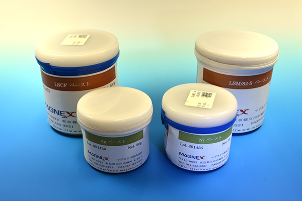
We can make a paste of the above powder. Please feel free to contact us.
We develop current collectors to maintain good electrical contact between SOFC/SOEC power generation cells and interconnectors. We also provide coating treatment to improve oxidation resistance and shape processing.
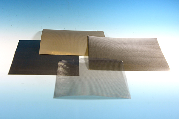
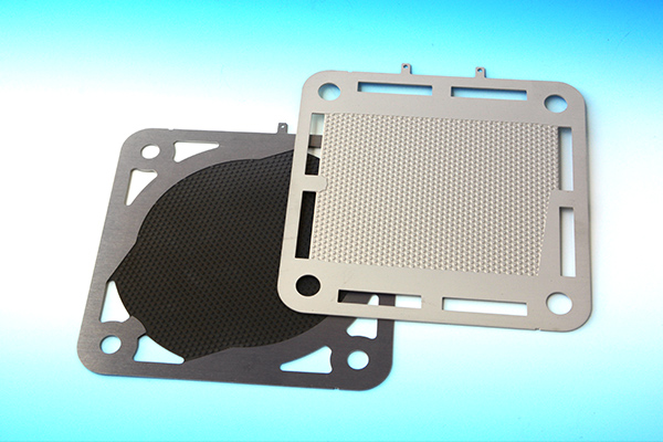
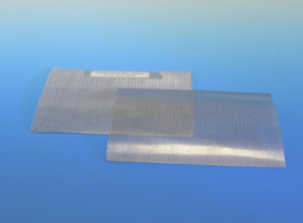
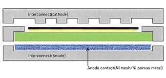
A metal mesh is inserted between the SOFC interconnector and the SOFC cell electrode to ensure contact between each, as shown in the figure below.
We offer a wide variety of materials and wire diameters, as well as plating surface treatment and other processing.
Various materials are available, including Crofer 22 APU interconnector alloys, pure Ni, and stainless steel.
Please make use of it to improve SOFC performance. We will process the shape.
| Material | Wire diameter (mm) | Number of meshes/inch (horizontal) | Number of meshes/inch (vertical) |
|---|---|---|---|
| Crofer 22 APU | Φ0.10 | 70 | 70 |
| Crofer 22 APU | Φ0.20 | 50 | 50 |
| Ni | Φ0.1~0.2 | 50~80 | 50~80 |
| SUS430 | Φ0.1~0.18 | 50~60 | 50~60 |
| SUS316L | Φ0.1~0.15 | 50~70 | 50~70 |
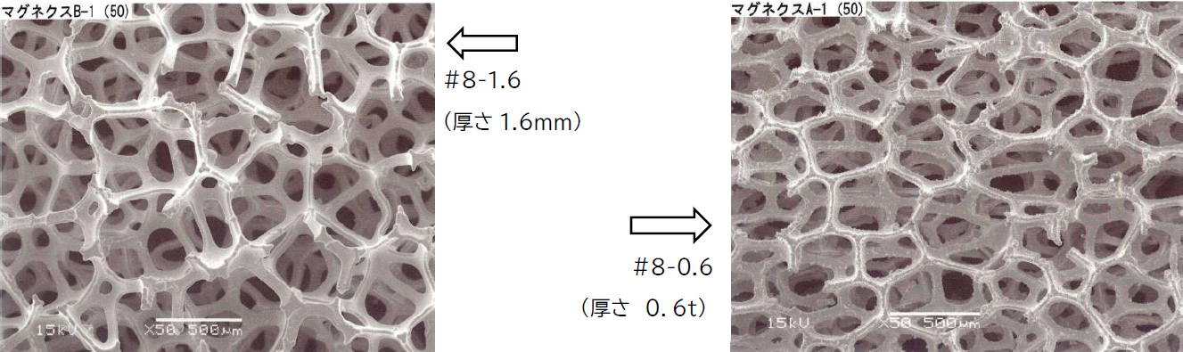
Unlike ordinary metals, porous metals (foamed metals) have pores inside, have low bulk density, and are easily deformed under pressure.
Therefore, like metal meshes, they are inserted between SOFC/SOEC interconnectors and SOFC/SOEC cell electrodes to improve conductivity by increasing the degree of contact and to solve contact resistance problems.
As materials, pure Ni, pure silver, and SUS430 porous metal are prepared as contact materials for SOFC/SOEC interconnectors.
| Material properties | SUS430 | Ni-1 | Ag | Ni-2 | |
|---|---|---|---|---|---|
| Thickness (mm) |
MAX | 10 | 15 | 2(Measured value) | 14 *4 |
| MIN | 0.8 *1 *2 | 1.6 *1 *2 | 0.8 *1 *3 | 0.6 *4 | |
| Dimensions (mm) |
MAX | 250×200 | 500×500 | 250×150 | 400×500 |
| MIN | 10×10 | 10×10 | 10×10 | 10×10 | |
*1…For meshes with large pore size (1.00mm, 1.27mm), the minimum thickness is 5mm and up.
*2…Thickness direction can be adjusted down to a minimum of 0.3 mm by press molding.
*3…Thickness direction can be adjusted by 0.5mm by press molding.
*4…1.4mm thick products are rolled by press. Thicknesses are 0.6/0.8/1.0/1.2/1.4mm.
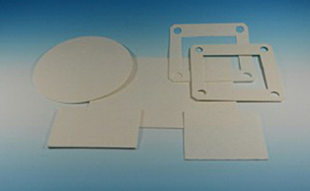
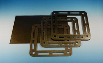
For SOFC, it is necessary to use the seal material for the purpose of protecting from mixing of the fuel and the air between SOFC inter connector and SOFC MEA, and further more, for the purpose of electric insulation. We are providing under mentioned two kinds of materials.
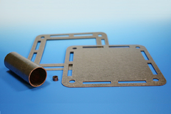
Mica is characterized by no swelling due to high-temperature heating and very little strength loss after heating.
It also has excellent water resistance and exhibits extremely high electrical insulation under high humidity.
Semi-hardened mica is not cured at room temperature, but is deformed by pressure and cured at 200°C to 250°C in 30 minutes to 1 hour.
Semi-hardened mica is available in 0.15t, 0.3t, 0.5t, and 1.0t thicknesses.
We will process to your desired size and shape.
This ceramic fiber is made by electrically fusing high-purity alumina and silica raw materials into fiber.
It has some elasticity, is gas permeable, and can be used as a high insulation material.
Thicknesses of 0.25/0.5/1/1.5/2/3mm are available.
We will process to your desired size and shape.